In an electric motor in Automation Systems, the motion that the motor is designed to generate can be decoded by means of a set of mathematical algorithms known as “Incremental Encoders”. These mathematical algorithms to translate the movement of the motor into electrical impulses, which can then be converted into the required voltage and current requirements for the motor to function correctly.
The amount of power that is needed for a particular motor depends on the value of the number of its inputs (the number of input voltage that the motor needs to operate). So in essence, the more current that the motor needs to operate at a certain temperature, the larger the size of the encoders needed to achieve this result.
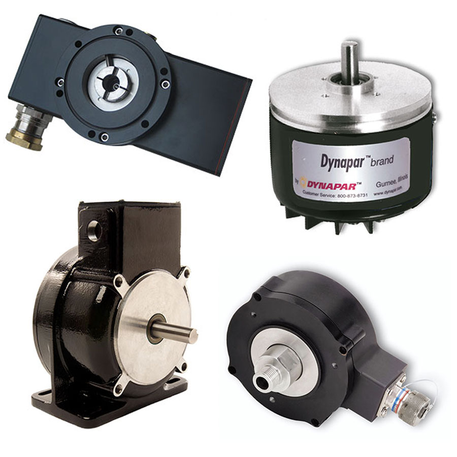
Basically, an incremental encoder is a rotary or linear electromagnetic device in automation systems which has two output signals, A & B, that signal pulses when the unit is moved. The A & B signals represent the movement of the unit and their position at any given time. They are generated by the non-volatile resistor that acts as a gate-switch that stops the current from flowing when it reaches a threshold value. In order to generate these pulses of electrical current, the incremental encoders are constructed such that their input terminals act like switches.
The threshold (resistance value) is set at a point by the control system so that current will not flow through the motor when the threshold is reached. The gate-switch then allows the current to start to flow only when the current at the input terminals is higher than the resistance value. In other words, if the input voltage is higher than the current that is required by the encoders, the gate-switch will allow the current to start. Then, when the current is allowed to flow, the rotational speed of the motor will decrease and the current will now be directed to the desired wire terminal. The incremental encoders are then used to control the motor rotation.
It can be convenient to use the same encoders to control the motor outputs in automation systems. This way, the encoders do not have to be reset to generate each output. By making use of different encoders for each motor, a wide range of motor outputs can be controlled. For example, in one instance, three separate encoders are used to provide alternating currents to the motor’s two output wires. If desired, the current generated at the output terminals can also be changed.
The advantage of using the same encoders for all steps is that it allows the same exact signals to be transmitted. This is an important factor for the smooth operation of a microprocessor. Of course, a microprocessor can only make use of the absolute power provided by the CPU. With the use of the incremental encoders, it is possible to regulate the power supplied to the motor thereby enabling the CPU to use only the fraction of the power necessary. Since the signals generated by the CPU are normally stable, such devices can be used to control the motor outputs to eliminate sudden spikes or drops in voltage.
The use of incremental encoders is especially useful when there are multiple stages in the process. As an example, in the manufacture of automobiles, it is common to convert the input signal of the electric motor into an analogue signal which is then sent to the rest of the machines. At each step in the process, it is important to convert the signal from one direction to another. In this case, it is ideal to use an encoder with a built-in step-preferred. In addition, such encoders can also be programmed to generate varying voltages on each input direction depending on the need.
However, before the use of incremental encoders in automation systems, it is important to consider how the signal is produced. The most common type of encoders works on the principle of bipolar distortion. This means that the incoming signal undergoes the first-order inverter. Once the first-order inverter receives a high-frequency input signal, it will change the incoming signal into a lower frequency. This method produces a strong signal but is relatively low power efficient because the output will have a fairly large amplitude as compared to the input signal.
On the other hand, bipolar encoders use the principle of angular momentum. For this process, a bipolar transistor is placed between the source and the output. When this happens, the transistor will slowly change its state and as it changes state, the current will change as well, resulting in a very strong current.
For the best Incremental Encoders in Australia visit GlobalMec Australia.